
Setting User Preferences
User-specific preferences can be specified by selecting Edit | Preferences.
Preferences can be set for:
At startup, VISRAD loads data from the Preferences
File. Data subsequently read in from Workspace
Files supersedes the preferences data.
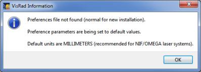
On startup, a check is made for the existence of the Preferences file. If it does not exist, the user is informed that all parameters set in the Preferences dialog will be set to their default values. This helps prevent situations in which a user installs VISRAD on a new computer, and is unaware that default values for the Preference parameters are now being used.
Note that when installing VISRAD on a new computer, users can copy the Preferences File from their old computer to avoid having to reset parameters.
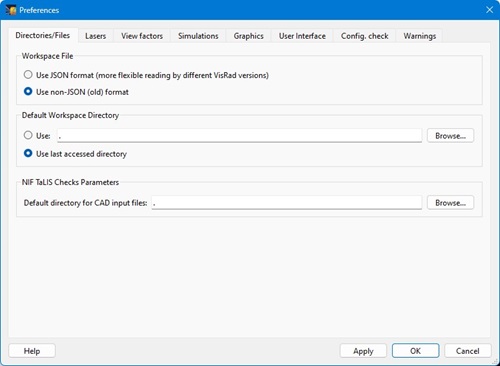
Files/Directories Tab
The Files/Directories tab is used to specify:
- The workspace file format (JSON or non-JSON).
- It is recommended that JSON-formatted files be used, as this option provides better support for reading/writing workspaces that use different versions of VISRAD. They also can be readily modified using scripting tools such as Python.
- The default directory for opening VISRAD workspaces. Options include: specifying a particular directory, and using the last directory accessed (i.e., the last directory for which a workspace was successfully opened).
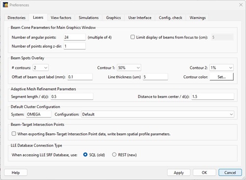
Lasers Tab
The Lasers tab contains parameters for:
- Displaying laser beam cones in the Main Graphics Window:
- To adjust the number of polygons used in rendering each beam cone, enter the number of points in the azimuthal direction and along the z-direction (i.e., beam propagation direction). The number along the z-direction refers to the number of points used from the beam port to the focus. The same number is used for the cone on the "far side" of the focus. Note that:
- the number of angle points used in generating each contour is equal to the number of angle points used in generating the beam cones
- using a larger number of polygons can result in a noticeable increase in CPU times needed in computing beam cone-target intersections
- Limit the extent (distance from focus) for which laser beam cones are rendered. (For NIF, this affects blue (3w) cones only.)
- Adjusting parameters for displaying Laser Beam Spot Overlays:
- Setting the number of contours to be displayed
- Setting the contour fractional intensity values
- Setting the default offset length to be used for the text labels for each spot (distance from beam spot center to text label)
- Setting the color and thickness of the iso-intensity contours
- Adjusting parameters for Adaptive Mesh Refinement (AMR) for laser power deposition calculations:
- Setting the surface element segment length criterion: If the maximum segment length of a subgrid element, scaled to the beam spot radius at the element position, exceeds this value, continue sub-division of that element.
- Setting the surface element distance criterion: If the distance of a subgrid element to the beam cone axis, scaled to the beam spot radius at the element position, is less than this value, continue sub-division of that element.
- Setting the default Laser Beam Cluster Configuration (separate entries are stored for each laser facility).
- Specifying that beam spatial profile parameters be written to the Beam-Target Intersection Points file.
- LLE users can specify if they wish to request SRF shot list information via the old SQL database system or the new network connection system
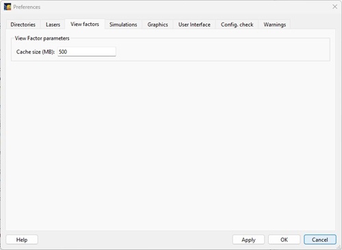
View Factors Tab
The View Factors tab contains parameters for:
- Cache size for storing view factor results (when size of cache is exceeded,
the least recently used view factor results are removed from memory).
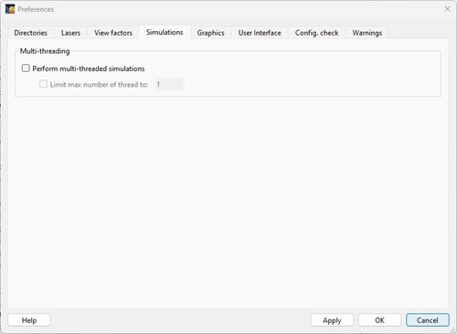
Simulations Tab
The Simulations tab contains parameters for:
- Specifying whether to perform multi-threaded simulations (suitable for multi-core desktop computers), and the maximum number of threads to use. This feature is supported on Mac Intel platforms, but not on Mac Power PC platforms.
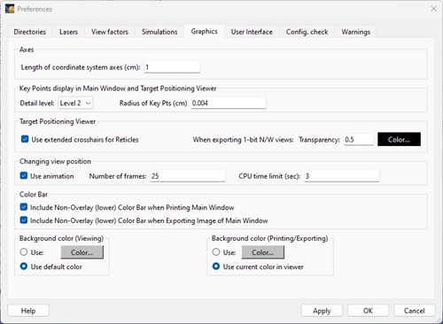
Graphics Tab
The Graphics tab contains parameters applicable to the Main Graphics Window:
- Axes parameters:
- Key Points displayed in the Main Graphics Window and Target Positioning Viewer:
- Detail level: Indicates how many key points are displayed (e.g., for "Level 2", midpoints along edges of Box objects as well as corners; for "Level 1", only corners are displayed)
- Radius of Key Points: size of key point spheres rendered.
- Target Positioning Viewer:
- Check box to use extended crosshairs for Reticles.
- Transparency (range from 0 to 1) and color used when exporting 1-bit N/W silhouette images.
- Parameters for changing the Viewing Position:
- Check Use Animation if migrating to each new view using multiple frames.
- Set the number of frames to use while migrating to a new view.
- Set the maximum CPU time to be used when migrating to a new view. If this time is exceeded, the view moves directly to the final (i.e., specified) view. (The parameter comes into play when either the views are extremely complex and need a long time to render or a large number of frames is used when migrating to a new view.
- Including the Color Bar that is located just below the Main Graphics Window when Printing or Exporting the image in the Main Graphics Window to a file.
- Setting the default background color in the Main Graphics Window. Separate default colors can be set for viewing and for printing/exporting images. The default color for Viewing is used when starting a new workspace. Note that the Viewing background color is stored in each Workspace File. Thus, when reading in an old Workspace File, the background color is set to the color stored in the file. To set the background color for the Main Graphics Frame to something different than the default viewing background color, select the Set | Background Color menu item.
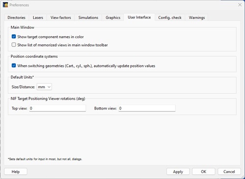
User Interface Tab
The User Interface tab contains parameters for:
- Showing the components in the Target Components List in color or black type.
- Showing/hiding list of Memorized Views in the Main Window toolbar.
- Automatically updating position coordinates in the Object Parameters Dialog (Position tab) and the Laser Beam Parameters Dialog (Pointing tab) when the Coordinate System geometry is changed.
- Setting the default units to be used when entering position and size data. (When a Preferences File is not available at start-up, the default value for units is mm).
- Setting custom rotation angles for the Top and Bottom views of the NIF TAS Viewer.
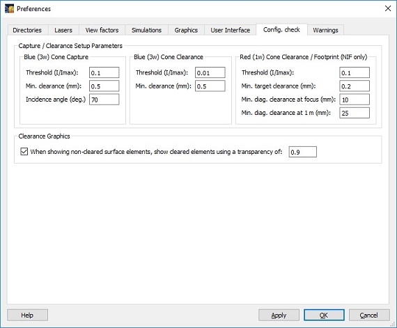
Configuration Checks Tab
The Configuration Checks tab is used to hold values of input parameters used in Laser Beam Capture/Clearance calculations. Note that these parameters are only used when clicking on the Set to Defaults button in the Set Capture/Clearance Parameters dialog box.
In the Laser-Target Capture/Clearance Report, when showing only non-cleared surface elements for a laser beam, the cleared surface elements can be displayed using a specified transparency (range 0 to 1).
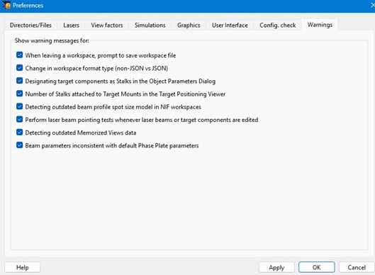
Warnings Tab
The Warnings tab is used to enable or disable the display of various warning or information messages.
Next
| Copyright © 2000-2026
Prism Computational Sciences, Inc. |
VISRAD 21.1.1 |